-
Description
The physical topology of the optical network may be quite complex. There can be several
possible physical connections between a start node and an end node for some (or for all)
traffic demands. The example discussed here involves the use of VPIlinkConfigurator GUI
capabilities and external algorithms which perform automatic routing though the Application
Programming Interface (API) of VPIlinkConfigurator.
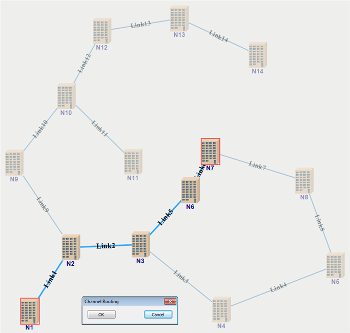
shows an example of network topology with the
given logical connections or traffic demands (TDs). In this graphic, two types
of TDs are displayed: green lines and brown lines, which correspond to routed and unrouted
channels respectively.
-
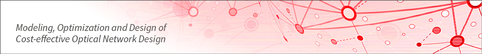
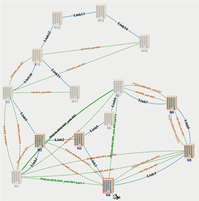
Automatic Routing
VPIlinkConfigurator (LC) offers several algorithms for automatic routing of primary
channels: minimize channel length, minimize hop number along the channel route and
minimize number of allocated wavelengths in the whole network. In addition,
the API interface allows you to realize other sophisticated routing algorithms.
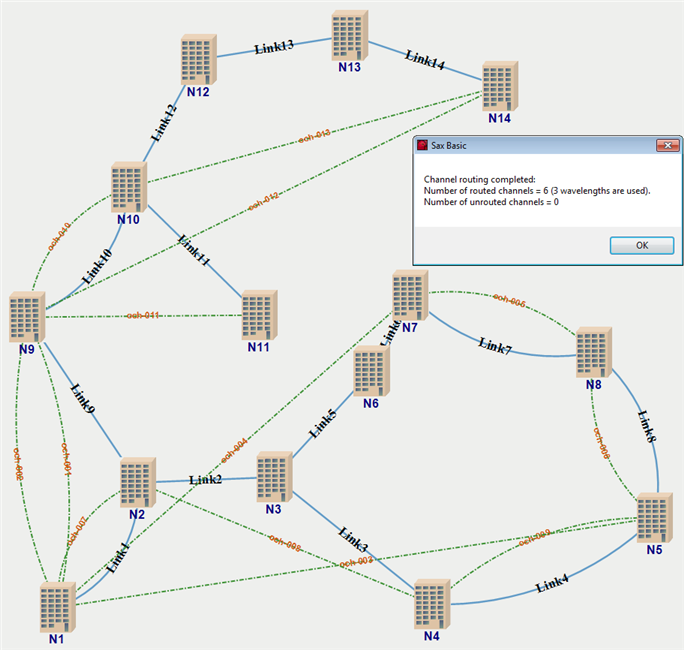
A channel protection algorithm realized using the API of LC can be used to establish
alternative channel routes once the traffic demands are routed. A protection channel is
created if an alternative path for a route of a primary channel exists.
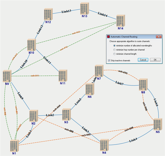
Typical results of automatic channel routing and protection channel routing are shown in
and
respectively.
-
Manual Routing
In some cases, the result of automatic channel routing does not correspond to the
desired logical topology. For example, it is more important to have link load
balancing rather than minimum number of allocated wavelengths. The topology editor
in LC provides a simple graphic way to establish an alternative route manually for
existing optical channels or for newly created logical connections. An example of
manual channel routing is shown in
.
-
Creation of the Optical Segments
In a network design containing many hops and long distances, OSNR
considerations very often dictate the establishment of regeneration points in the middle of
some traffic demands. In the Graph view, logical connections can be segmented to accommodate
a regeneration point by simply using the Split Channel tool on individual channels or
groups of channels, as shown in
.
-
Further Information
Keywords: Optical Network Design, Traffic Demands, Channel Routing, Primary Channels, Protection Channels, Optical Segments, Regeneration Points, Application Programming Interface (API), Design Automation, Scripting
Examples describing other steps of the design workflow are available in the WDM Network Design section.