-
Description
Every service provider and equipment vendor has their favorite methods for visualizing network designs. This often involves simple MS Office programs such as Visio.
The problem is porting this graphical representation into an advanced link engineering tool such as VPIlinkConfigurator. The example discussed here involves the use of the standard API interface of VPIlinkConfigurator (LC) to accomplish fully interactive applications involving a Visio graphical front-end and LC to do the heavy lifting in the design and analysis of the links.
While LC provides for scripting in an integrated shell using Visual Basic (VB) or Python, the application is also exposed as a COM object.
Interestingly, both approaches can be simultaneously utilized so that the most appropriate partitioning of the solution can be supported.
-
Creation of the Physical Topology
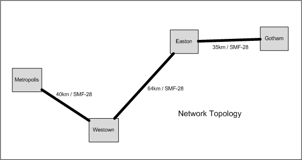
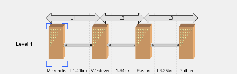
In this example, consider the Visio link drawing shown in . In this graphic, there are two types of drawing objects: nodes containing the equipment, and fiber paths. A VB script can easily be written to find the endpoints of the link and sort the objects in the Node-Fiber-Node order. Once this is done, another portion of the VB script in Visio can take this information and create the topology in LC that accurately represents the nodes and fiber type and length. shows the physical layer topology in LC created by a VB script in Visio.
-
Creation of the Logical Topology
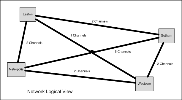
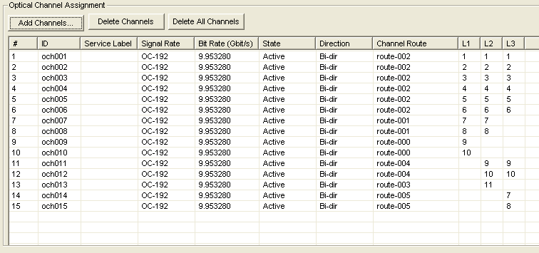
The next step is the creation of the channel plan in LC. This can be derived by a graphic, as shown in . The VB script in Visio can easily construct a table of nodes and traffic or channels between these nodes. Once this is done, the Visio VB script can then create the channel plan derived from this graphical representation of the logical view of the network. shows the resultant channel plan for this topology.
-
Design
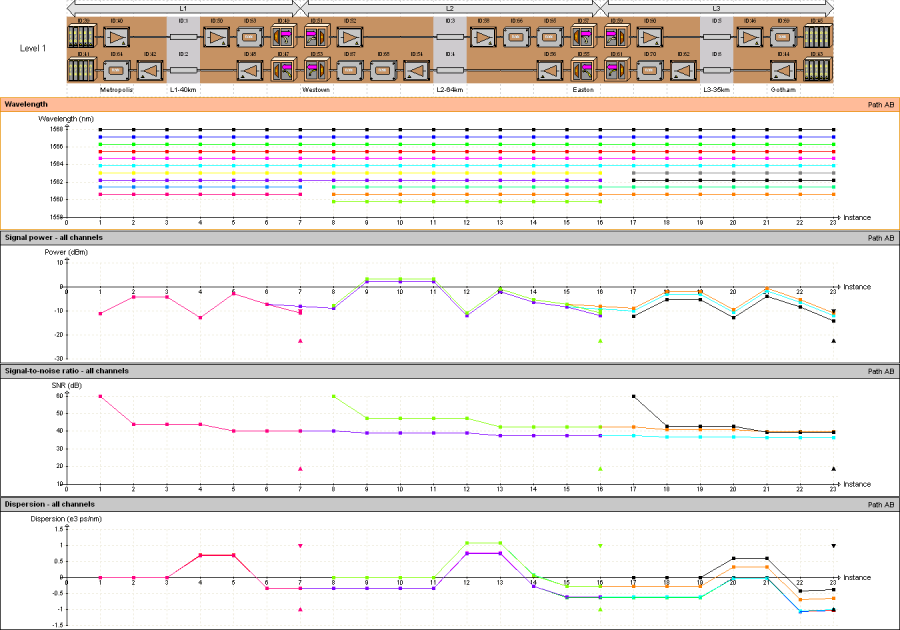
It is important to note that up to this point no scripts were run in the scripting shell which is part of the LC application. Both the Topology and Channel Plan were created by a VB script running in Visio. This script took full control of the LC application through the API interface. However, it is at this point that remaining portion of the design task, namely the synthesis of the link and the placement of equipment, is best done in LC. In this example, the Visio script can initiate the execution of a Python script running in LC, which will optimize the placement of the equipment. After this is complete, all the equipment is placed, and the performance milestones are met, and maps can be generated showing signal power, OSNR and dispersion, just to name a few. shows the result of this step.
-
Possibilities
At this point it is important to realize that the use of the API interface allows for endless possibilities for design automation using the powerful synthesis, analysis and reporting tools of VPILinkConfigurator. Virtually any MS Office application, including Excel, Visio or Access, can be utilized. Any application that can manipulate COM objects can interface with LC, so an interface can be built to interact with virtually any graphics tool, database or other custom application.
-
Further Information
Keywords: DWDM Link Design, Automation, Application Programming Interface (API), Scripting
Similar demonstrations are available in the VPIlinkConfigurator Examples section.