Automatic Equipment Placement in Mesh Network

  • Description

    Once the topology, channel plan and add/drop equipment have been established (that is, an initial WDM system has been created), items may be taken from an assigned library of equipment and placed in the nodes. Importantly, the placement of amplifiers, attenuators and dispersion compensating elements (DCMs) has to be done to keep the link performance, optical powers, accumulated dispersion and OSNR, for example, within the equipment capability, as shown in Figure 1. This process can be quite tedious for complex WDM networks. An alternative approach is an automated equipment placement through the use of the Application Programming Interface (API) of VPIlinkConfigurator(LC). The Scripts automating the optical equipment configuration can be written to take into account both link performance and cost in the optimization process.

  • Typical Results

    The automated link loss and accumulated dispersion compensation includes several steps:

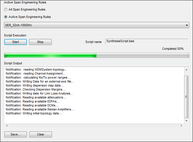
    • Validation of initial configuration of WDM system; the script checks whether all channels are routed and transceivers are selected, whether amplifiers and DCMs are required. Figure 2 shows a Script Output window with messages generated by the script while the initial WDM system is being validated.

    • Placement of amplifiers and DCMs on a link-by-link basis taking into account express channels incoming from adjacent links. Power equalization is performed at this step if it is required.

    • Evaluation of system performance, i.e., the validation of signal power, accumulated chromatic dispersion, OSNR for each optical channel against system requirements and equipment capability is done.

    • Figure 3 
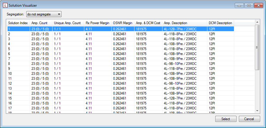
shows the result of the next step when the list of solutions with key metrics such as receiver margins, cost of added equipment, number of added amplifiers and/or DCMs is generated. One or several solutions can be selected at this step to get the corresponding configurations of optical equipment in the LC design package.

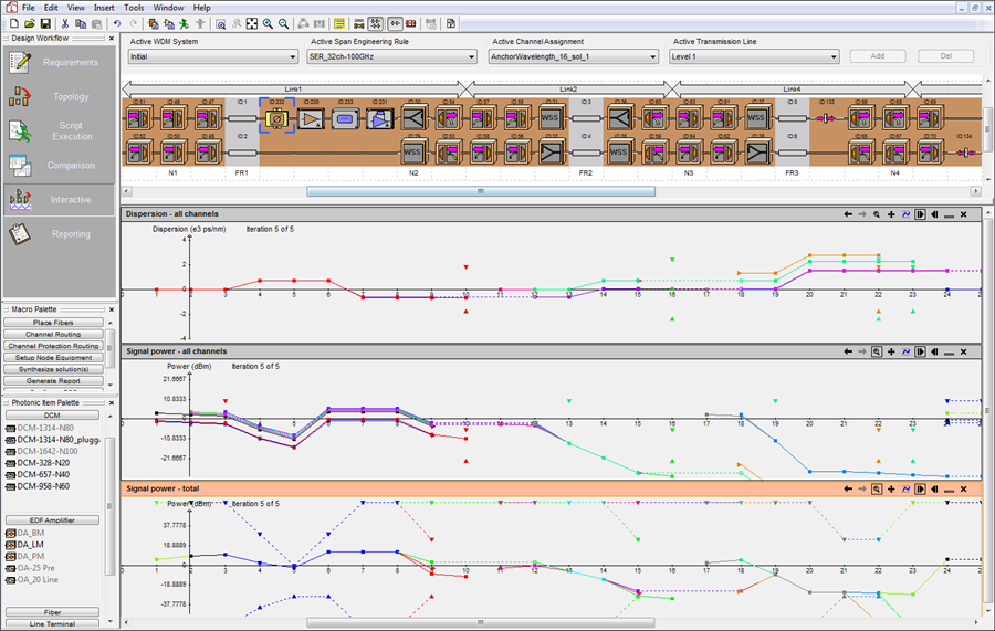
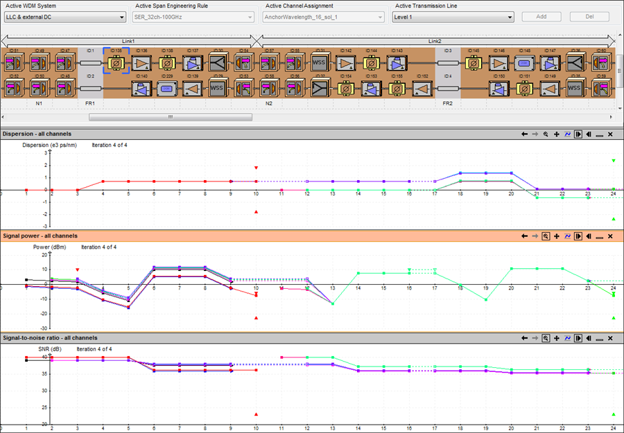
    • Once solutions are selected, a new WDM system is created for each selected solution. Figure 4 shows the results of the script-driven equipment placement process. In addition, it shows a set of plots of system performance metrics as maps.

    Further steps of system design workflow include the detailed Performance Analysis and Report Generation using the built-in functionality of LC or customized reporting macro realized via API.

  • Possibilities

    • Select various sets of equipment and define versatile operating conditions or performance constrains to generate required solutions

    • Select equalization type for express channels at a branch point

    • Proprietary algorithms can be used to perform link loss and dispersion compensation

    • Validate system performance for different equipment configurations

        • Design WDM network manually with instant system performance evaluation

  • Further Information

    Keywords: Link Loss Compensation, Automatic Equipment Placement, In-line Amplifier Placement, Channel Equalization, Design Automation, Application Programming Interface (API), Dispersion Compensation, Link Engineering Rules, Optical Equipment Configuration, Ring Simulation

    Examples describing other steps of the design workflow are available in the WDM Network Design section.

« back to other examples