Equipment Configuration: Add/Drop Equipment, Wavelength Utilization, Transceiver Allocation

  • Description

    The assignment of a specific wavelength to some optical channel, allocation of add/drop equipment and selection of appropriate transceivers are quite interdependent tasks. Please note that the available wavelengths are restricted by a set of available equipment, i.e., OADM, Mux/DeMux, WSS and other add/drop devices specified as a part of Span Engineering Rules Package. Such devices may use either CWDM or WDM channel plans (e.g., from 25 GHz to 200 GHz grid) or even hybrid channel plan. Various configurations of the add/drop equipment can be chosen for the whole network in accordance with the channel plans considered, for example, a configuration with the lowest cost or a configuration with the most compact wavelength plan can be considered as the most optimal one.

  • Typical Results

    The allocation of add/drop equipment includes several tasks which should be considered simultaneously to build the most optimal equipment configuration for the whole WDM network (Figure 1):

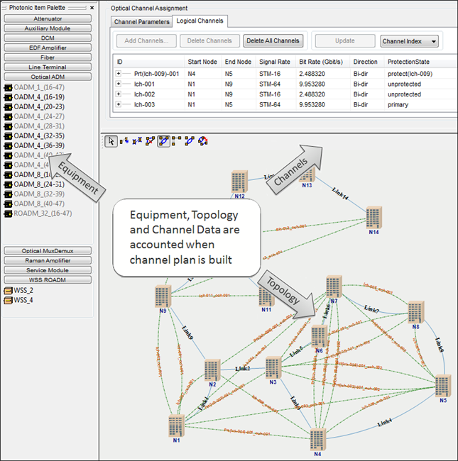
    • Creation of possible configurations of add/drop devices for each node of the network

    • Calculation of feasible wavelength assignment for each add/drop configuration

    • Selection of the transceiver equipment, which may strongly depend on wavelength, bit rate and other channel characteristics. Dispersion margins of the receiver are also taken into account at this step

    All these tasks are automated in the Node Configuration Macro application (NCM) which is realized via the Application Programming Interface of VPIlinkConfigurator. The NCM utilizes powerful and robust algorithms for wavelength assignment and transceiver selection when it configures add/drop equipment. It is organized as a wizard application guiding the user through the following three steps of the add/drop equipment configuration workflow:

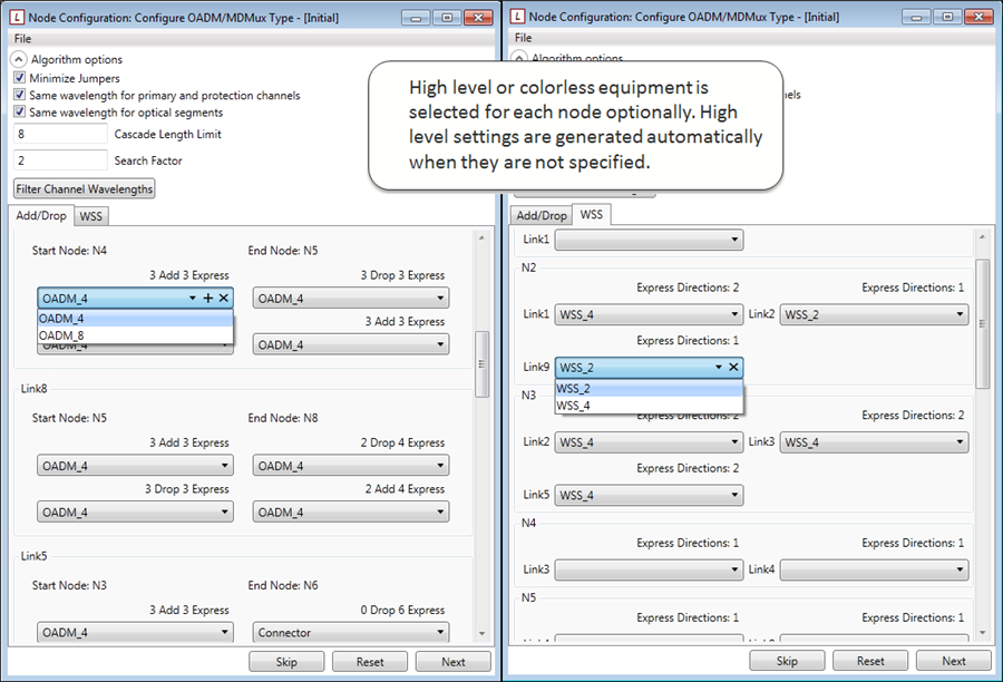
    • Optional definition of high-level or colorless requirements for add/drop equipment in nodes, as shown in Figure 2

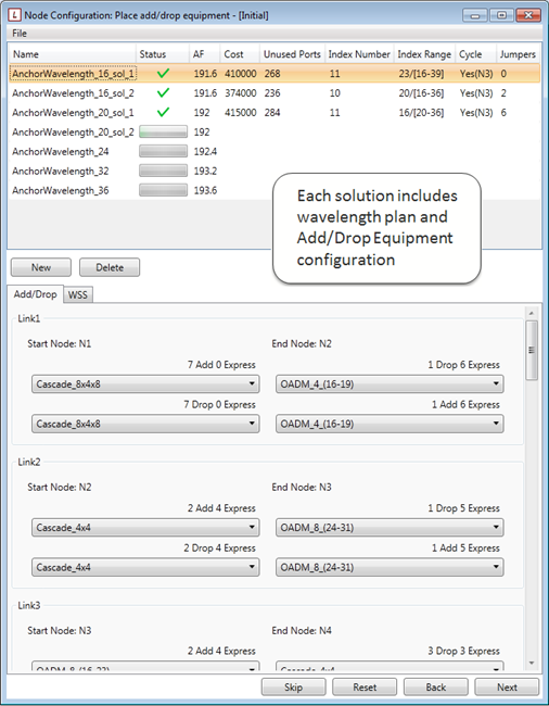
    • At the next step, solutions including both the assignment of channels to particular wavelength and selected OADM, MDMux and WSS devices are generated automatically (see Figure 3)

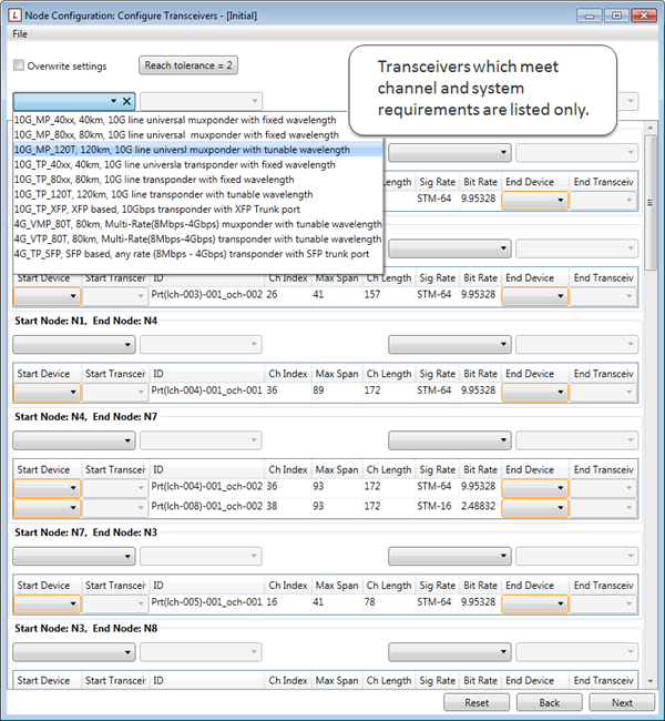
    • The appropriate transceivers are selected for each optical channel at the last step, as shown in Figure 4. The NCM generates a list of compatible transceivers for each terminal facility taking into account the channel wavelength, bit rate, transceiver form factor (SFP, XFP, etc.) and other system parameters

    Figure 5 
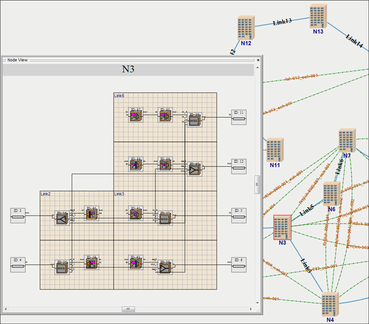
shows an automatically generated add/drop equipment configuration for one of the nodes in the system.

  • Possibilities

    • Mux/DeMux, MDMux, OADM, ROADM, Cascaded OADM and WSS architectures are modeled

    • NCM offers several options to build the most appropriate solution with either minimal number of jumpers or compact wavelength plan with or without the utilization of cascaded OADMs or WSS ROADMs

    • NCM allows for manual design of the add/drop equipment in the WDM network on a node-by-node basis

  • Further Information

    Keywords: ROADM, OADM configuration, WSS, Wavelength Assignment, Channel Plan, Transponder, Muxponder, Pluggable Optics and Transceiver Selection, DWDM Network Design

    Examples describing other steps of the design workflow are available in the WDM Network Design section.

« back to other examples