-
Description
High-speed systems transmitting 100 Gbps on a single wavelength is the next
technological step for integrating Ethernet traffic into metro and long haul networks. Several
modulation technologies are being investigated at the moment. 100-Gbps transmission using binary
modulation formats (NRZ, Duobinary or NRZ/VSB) might be easier to realize compared to the approaches
using multilevel modulation formats. Further on, they might be more attractive from an economic
point of view due to the simplicity of their transmitter and receiver structures. However,
binary formats show increased requirements on electrical and electro-optical components, as
electrical signals with a ~100-GHz bandwidth must be managed. The increase of speed of electronics
enables the multiplexing of signals in the electrical domain (ETDM), and thus, the implementation
of high-speed ETDM channels.
This example shows how data channels can be multiplexed in the electrical time domain and how to
model the electronics in an ETDM transmitter to represent impairments such as electrical bandwidth
and clock imperfections.
-
Typical Results
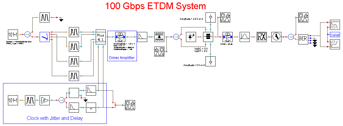
The setup of an Electrical Time Division Multiplexing (ETDM) system with
4 channels at 25 Gbps is represented in
.
The ETDM 100-Gbps signal is generated by 4x25-Gbps tributaries and two 2:1-stage electronic
multiplexers, consisting of ideal logical gates. The driver amplifier adjusts the signal
delivered by the electronic multiplexer, which is in the order of millivolts, to the level
required by the modulator (usually in the order of volts). A Mach-Zehnder modulator (MZM)
is driven with the adjusted 100-Gbps signal. Electrical filters represent amplitude ripple
and nonlinear phase response of the amplifier and the electrical response of the MZM.
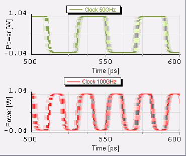
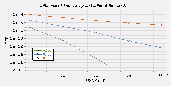
Clock imperfections are modeled by adding a source with pseudorandom jitter to an ideal
clock signal. Delays between the clock and data signals are represented by a deterministic
delay ().
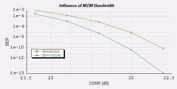
The impact of the MZM bandwidth limitation is investigated by varying the bandwidth of the
electrical filters. Simulation results are represented in
and
,
showing a penalty on the allowed OSNR.
-
Further Information
Keywords: Electrical Time Division Multiplexing (ETDM), transmitter electronics, MZM, optical clock, high-speed systems
Similar demonstrations are available in VPItransmissionMaker Optical Systems and on the VPIphotonics Forum.