
Arrayed Waveguide Grating with Flat-top Spectral Response
This demo illustrates how Arrayed Waveguide Grating (AWG) can be simulated employing StarCoupler, WgStraight and MapGr modules. This schematic provides us with advanced methods of AWG design. As an example multigrating method is used to achieve a flattened spectral response. Within this approach the grating between star couplers is separated into two sub-gratings: each has its own length increment and central wavelength. If these two peaks are slightly different, the final spectral response is flattened. 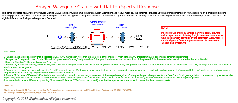
» Keywords: Arrayed Waveguide Grating, Multiplexer, PICs, AWG, Optical planar waveguide components, Star Coupler, Photonic Integrated Circuits
» Available in: Photonic Circuits Demos
Bend-Induced Losses in Quarter-Circle Waveguide
This demo illustrates how the bend-induced attenuation and mode coupling can be modeled employing the WgBend module. The pure bend-induced loss in a quarter-circle waveguide is measured as a function of the bend radius. The demo illustrates both known effects: strong polarization dependence of the bend-induced losses and their oscillatory dependence on the bend radius due to the bend-induced mode coupling. 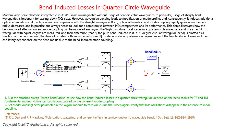
» Keywords: Attenuation, Bent Waveguide, PICs., Curvature, Waveguide Bend, Mode Coupling, Photonic Integrated Circuits
» Available in: Photonic Circuits Demos
Characterization of Optical Filters with SpectrumAnalyzer
Illustrates the usage of cosimulated galaxy "SpectrumAnalyzer" for quantitative characterization of the optical filters properties, such as the number and locations of the filter peaks and dips, their central frequencies, bandwidths at the specified level, ripples inside the specified pasbands around the filter central frequencies, and so on. 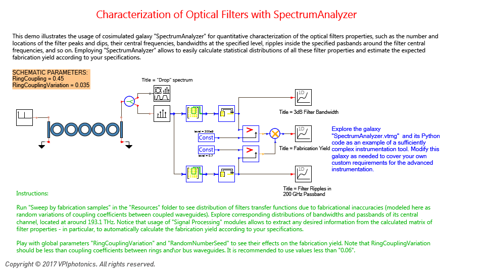
» Keywords: Instrumentation, Python, Filter Characterization, SMATRIX, Flat Passband, Add-drop Filter, Microring, Ring Resonator
» Available in: Photonic Circuits Demos
Design of Apodized Linearly Chirped Bragg Gratings for Dispersion Compensation
This demo illustrates usage of WgGrating module for modeling waveguide or fiber Bragg gratings with arbitrary user-defined apodization and chirp profiles. Three linearly chirped gratings are compared: with no apodization, with Gaussian apodization, and with Sinc apodization, designed with the goal to compensate dispersion for 100 km standard fiber (that is, 1600 ps/nm). In agreement with [1], the Sinc apodization function provides the best results for short gratings. 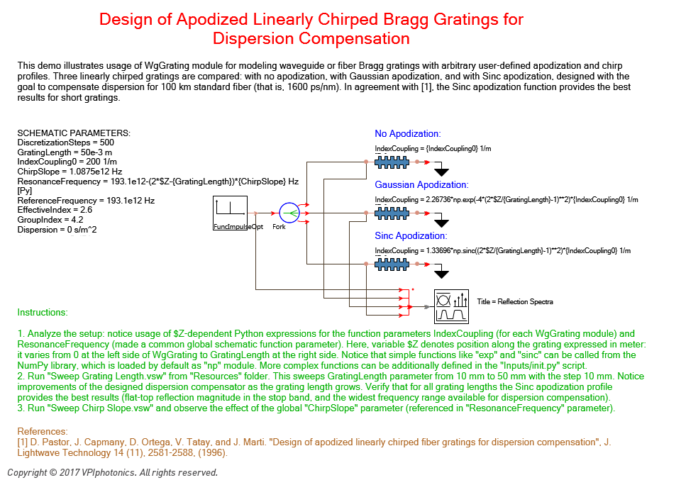
» Keywords: Apodized, Dispersion Compensation, Chirped, Bragg, Apodization, Grating
» Available in: Photonic Circuits Demos
High-Order Microring Add-Drop Filter with Flat Passband
Shows that properly designed high-order microring add-drop filters are characterized by improved passband characteristics and larger out-of-band signal rejection. The demo also illustrates a multi-iteration technique that can be used for Periodic Block Mode simulations of photonic integrated circuits with feedback loops. 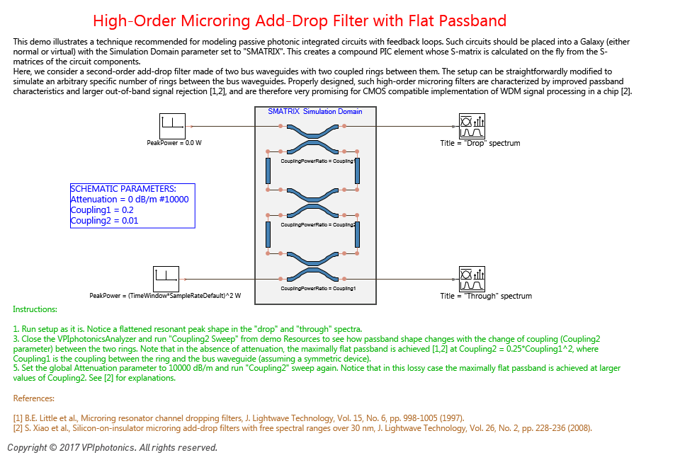
» Keywords: Simulation Deadlock, Multiple Iterations, Flat Passband, Add-drop Filter, Microring, Ring Resonator
» Available in: Photonic Circuits Demos
Induced Transparency in Cross-Coupled Two-Ring Photonic Switching Element
A system that consist of a waveguide intersection, positioned between two ring resonators, becomes popular as an efficient photonic switching element that allows to control routing of signals in optical networks and interconnections. This demo illustrates functionality of such a switching element in its "On" state and shows that it can exhibit even more interesting effect: a coupled-resonator-induced transparency (CRIT) - an all-optical analogue to electromagnetically induced transparency, initially discovered for a system of two consecutive ring resonators (see demo "Coupled-Resonator-Induced Transparency"). 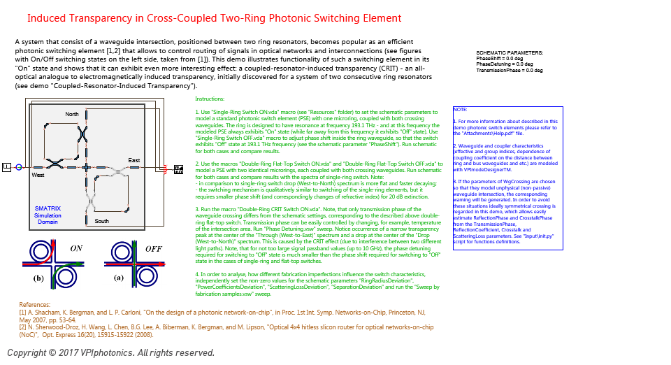
» Keywords: WgCrossing, EIT, Waveguide intersection, Coupled-Resonator-Induced Transparency, Electromagnetically Induced Transparency, CRIT, Microring
» Available in: Photonic Circuits Demos
Hybrid Time-and-Frequency-Domain Modelling
of Arrayed Waveguide Gratings
This demo illustrates how Arrayed Waveguide Grating (AWG) can be simulated in time-domain employing the SMATRIX simulation domain. It also illustrates how the Digital Filter and Visualization parameters can be added to the SMATRIX-domain galaxies to control FIR filter design and to save the S-matrix of the compound passive device. 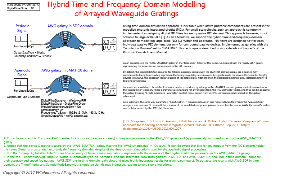
» Keywords: Arrayed Waveguide Grating, Time-and-frequency-domain, PICs, SMATRIX, AWG, Photonic Integrated Circuits
» Available in: Photonic Circuits Demos
WgGrating as Cosimulated PIC Element: Frequency Domain vs Time Domain and Python vs C++
Demo illustrates how custom PIC Elements can be created using Python or C++ cosimulation with the PIC_CoSimInterface module. Such custom modules support both, SDF and SMATRIX simulation domains, they can process Periodic and Aperiodic Block signals as well as Sampled-Mode signals, and they can load and/or save the device S-matrix. 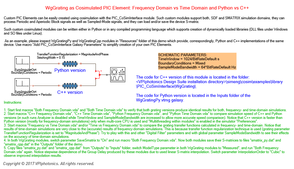
» Keywords: Cosimulated, PIC, Time-Domain, Element, Frequency-Domain
» Available in: Photonic Circuits Demos